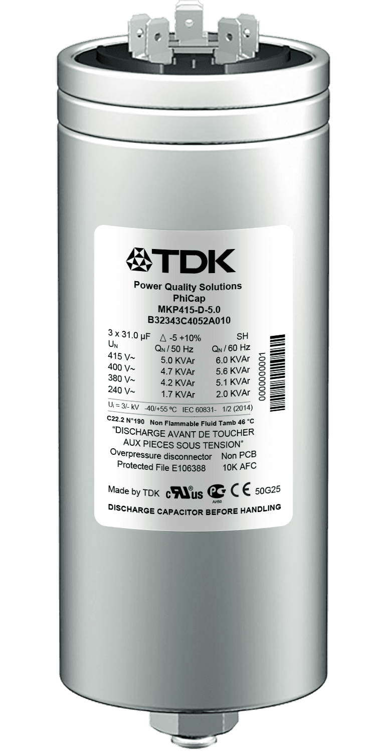
PhiCap
Power capacitor, MKP series (B32340C / B32343C / B32344E) · EPCOS AG / TDK Electronics
PhiCap is the long-established MKP capacitor line from EPCOS / TDK Electronics, in power factor correction service for over fifteen years and the usual choice for the smaller and mid-sized steps of a compensation panel. The winding is metallized polypropylene film with a stacked winding, impregnated with a semi-dry biodegradable soft resin and housed in a cylindrical extruded aluminium can with a threaded mounting stud on the base. The three-phase types are delta-connected and supplied with the discharge resistor included — pre-mounted on the B32344 series. As on the larger PhaseCap, two independent safety principles apply: the film is self-healing, and an overpressure disconnector removes the capacitor from the network at end of life. The reactive power range runs from 0.5 to 30.0 kvar per can for three-phase types and 0.7 to 6.4 kvar for single-phase types, across a voltage range of 230 to 525 V.
Key Features
- 01Voltage range 230 … 525 V, output range 0.5 … 30 kvar three-phase (0.7 … 6.4 kvar single-phase)
- 02Long life expectancy of up to 130 000 hours at temperature class −40/C
- 03High pulse current withstand capability: up to 200 × IN
- 04Low losses: dielectric < 0.2 W/kvar, total < 0.45 W/kvar
- 05Dual safety system: self-healing film plus overpressure disconnector
- 06Shock-hazard protected optimized capacitor safety terminal on the B32344 series
- 07Compact cylindrical aluminium can with stud — low weight, easy installation, maintenance-free
- 08Discharge resistor included, pre-mounted on the B32344 series
Applications
- Low Voltage Reactive Power Compensation SolutionsIn industrial and commercial facilities the reactive power balance can be upset both by inductive loads such as motors and transformers and by loads with a capacitive effect such as UPS systems, drives and long cable runs. This can disturb the reactive power balance, move the power factor away from the desired level, draw unnecessary current from the network, increase losses and incur reactive energy charges. Low voltage compensation systems hold the power factor at the desired level by providing compensation matched to the facility's inductive or capacitive reactive power demand. Where load changes are rapid, thyristor-switched systems are used to respond quickly to reactive power variation. In facilities where harmonics are present, compensation systems with harmonic filter reactors are applied to keep the capacitors from entering resonance with the network. A correctly engineered compensation system helps to avoid reactive energy charges, to use transformer and cable capacity more effectively, to reduce electrical losses and to improve system performance.
- Medium Voltage Reactive Power Compensation SolutionsMedium voltage compensation systems hold the power factor at the desired level in high-power industrial facilities by supplying the reactive power that inductive loads require within the plant itself. This reduces the reactive power drawn from the network, lowers electrical losses and makes more efficient use of existing system capacity. MV compensation systems can use fixed or automatically stepped capacitor banks according to the needs of the facility. Switching is carried out by vacuum contactors or circuit breakers, and the system is operated safely with appropriate protection and control equipment. Because every facility has a different network structure, load characteristic and reactive power demand, MV compensation systems are engineered specifically for the site rather than supplied as a standard solution. Capacitor rating, step structure, switching devices, the protection system and, where required, series reactors are determined from the measurement and engineering work carried out, producing a compensation system suited to the facility's operating conditions.
Technical Specifications
PhiCap
| Series / ordering code | MKP; B32343C and B32344E (three-phase), B32340C (single-phase) — individual types per the type tables in the PFC Product Profile 2025, pages 48 … 52 |
|---|---|
| Rated voltage VN | 230 … 525 V AC (230 / 400 / 415 / 440 / 480 / 525 V) |
| Rated output QN | 0.5 … 30.0 kvar per can, three-phase; 0.7 … 6.4 kvar per can, single-phase |
| Connection | Three-phase, delta (D); single-phase types also available |
| Construction | Metallized polypropylene film, MKP technology with stacked winding, extruded aluminium can with stud |
| Impregnation | Biodegradable soft resin, semi-dry |
| Capacitance tolerance | −5 % / +10 % |
| Rated frequency | 50 / 60 Hz |
| Maximum permissible voltage Vmax | VN +10 % (8 h/day), +15 % (30 min/day), +20 % (5 min/day), +30 % (1 min/day) |
| Maximum permissible current Imax | Up to 1.5 × IN, including combined effects of harmonics, overvoltage and capacitance |
| Inrush current IS | Up to 200 × IN |
| Losses | Dielectric < 0.2 W/kvar; total < 0.45 W/kvar (excluding discharge resistor) |
| Mean life expectancy tLD | Up to 130 000 h at temperature class −40/C; up to 100 000 h at temperature class −40/D |
| Number of switching operations | Max. 5000 per year to IEC 60831-1,2 |
| Ambient temperature | −40/D: max. +55 °C, 24 h mean +45 °C, 1 year mean +35 °C, lowest −40 °C |
| Voltage test terminal / terminal VTT | 2.15 × VN, AC, 2 s |
| Voltage test terminal / case VTC | 3000 V AC, 10 s |
| Safety | Self-healing technology, overpressure disconnector, maximum allowed fault current 10 000 A to UL 810 |
| Discharge device | Discharge resistor included; pre-mounted on the B32344 series |
| Terminals | Optimized capacitor safety terminals on the B32344 series, max. current 50 A, max. 16 mm² cable cross-section; fast-on terminals on the B32340 and B32343 series |
| Mounting and grounding | Upright; threaded M12 stud (10 Nm) for can diameters above 53 mm, M8 (4 Nm) for 53 mm and below |
| Enclosure | IP00 for B32340 / B32343, indoor mounting; IP54 for B32344 with plastic terminal cap |
| Cooling / humidity / altitude | Natural or forced / max. 95 % relative, non-condensing / max. 4000 m above sea level |
| Certification | cUL file # E106388; CSA C22.2 No. 190 MC # 236094 (up to ø 85 mm); GOST |
| Standards | IEC 60831-1,2; UL 810 5th edition |
Technical values are taken from the manufacturer's published documentation. Confirm against the current datasheet before ordering.
Downloads
Datasheets, manuals and technical documentation are available from the manufacturer's document centre, or on request from us.
Technical sources
- www.tdk-electronics.tdk.com/download/174004/af7615a46f93c0fa639ca0b108748f46/pfc-katalog-pp.pdf
- www.tdk-electronics.tdk.com/download/174082/377003129cb5bbb6c845dbc039e2a780/pfc-phicap-pb.pdf
- www.tdk-electronics.tdk.com/download/530866/c04790d3d6dfa3d84c405431d221a33e/pdf-installationandmaintenancephicap.pdf
Related Products
Capacitors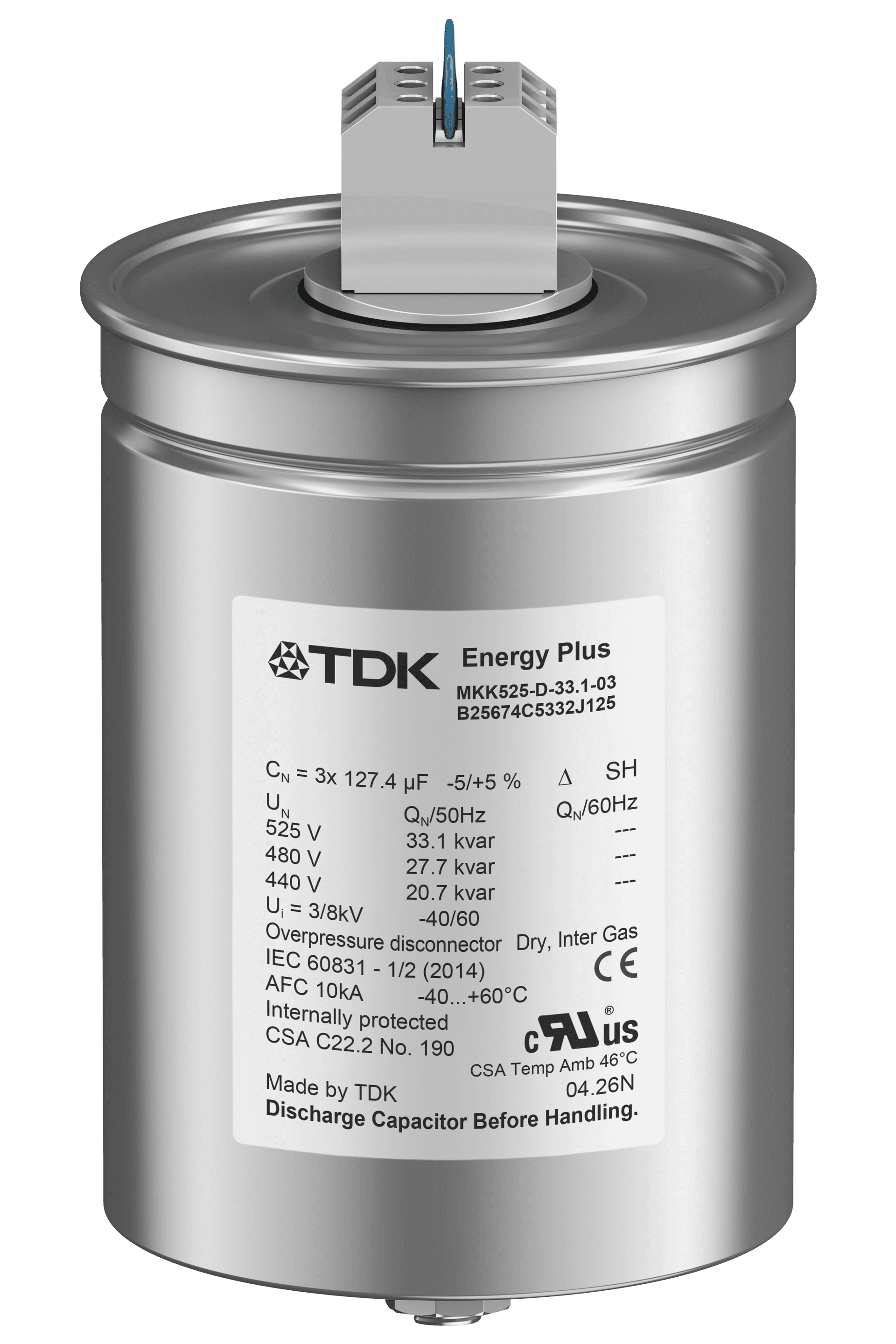
EPCOS
PhaseCap Energy Plus (Resin)
Power capacitor, MKK series (B25675C), semi-dry biodegradable resin · EPCOS AG / TDK Electronics
EPCOS
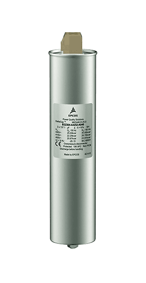
DeltaCap
Power capacitor, MKD series (B32304A), 480 V / 33 kvar · EPCOS AG / TDK Electronics

EPCOS
PQSine S
Active harmonic filter and power optimizer, PQSine S series (B44066F*S) · EPCOS AG / TDK Electronics
Get in Touch
Contact us about this product
Let us work out the right model for your application. Share your single-line diagram or measurement data and our technical team will review it.