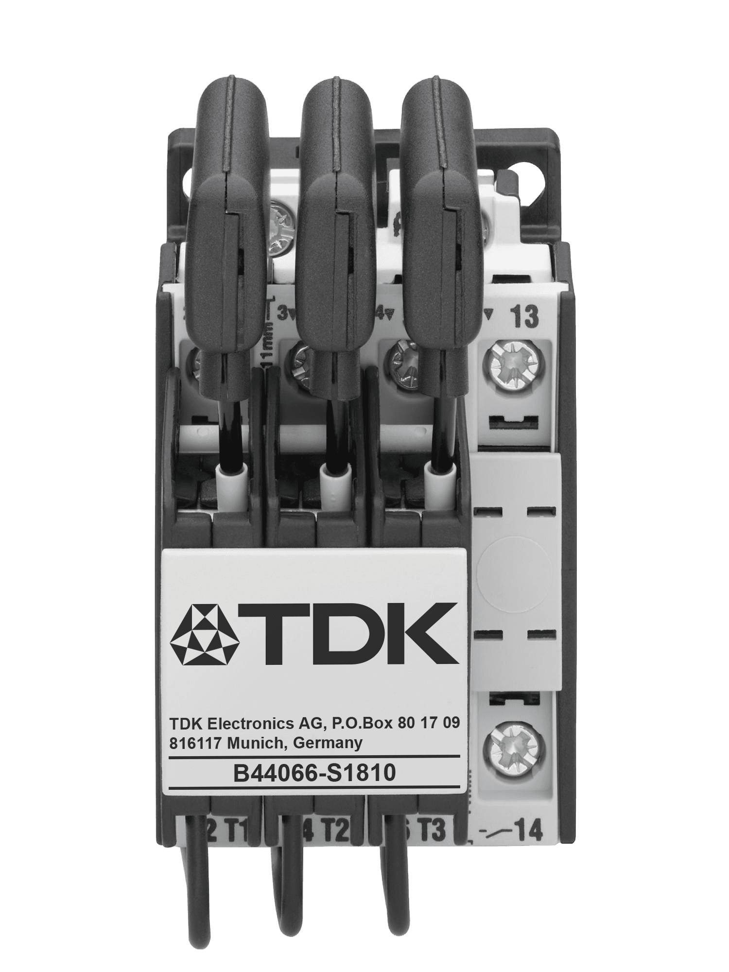
B44066S
Capacitor contactors, B44066S series, 12.5 … 100 kvar · EPCOS AG / TDK Electronics
When a capacitor is switched onto an AC network the result is a resonant circuit, and the inrush current can reach a multiple of the rated current — worse still when the step is switched in parallel with others already on the line and the short-circuit power at that point is high. The B44066S series answers that: these are contactors built for utilization category AC-6b, the switching of three-phase capacitors, not for motor duty. Leading contacts with damping resistors close before the main contacts and pre-charge the capacitor, so the current peak never forms. The panel gains twice over — the voltage sag and the transients that a hard connection would produce are avoided, and the main contacts and the capacitors themselves last considerably longer. The series runs from 12.5 to 100 kvar at 400 V, up to 148 kvar at 690 V, across eight frames. Epkom holds the three smallest — S1810, S2410 and S3210 — which cover the step sizes most low-voltage compensation panels are built from; the larger frames are available to order. All types are three-pole with one NO auxiliary contact, with the damping resistors tamper-proof and protected.
Key Features
- 01Utilization category AC-6b for switching three-phase capacitors; voltage range 400 … 690 V
- 02Output range 12.5 … 100 kvar at 400 V; up to 148 kvar at 690 V
- 03Excellent damping of inrush current through leading contacts with pre-charging resistors
- 04Leading contacts with wiper function, pre-contacts with snap function — soft switching, longer capacitor life
- 05Tamper-proof and protected resistors; reduced ohmic losses
- 06Improved power quality: transients and voltage sags on switching are avoided
- 071 NO auxiliary contact on every type; easy access for cable connection
- 08cUL file 224924 and CCC (China Compulsory Certification) approvals
Technical Specifications
B44066S
| Series / ordering code | B44066S****J230 (220 … 240 V coil) and B44066S****J110 (110 V coil); S3210 and S6210 also available as …J400 (380 … 415 V coil) |
|---|---|
| Types held by Epkom | B44066S1810, B44066S2410, B44066S3210 |
| Full series | S1810, S2410, S3210, S5010, S6210, S7410, S9010, S9910 |
| Capacitor power at 380 … 400 V, +50 °C | S1810 0…12.5 · S2410 10…20 · S3210 10…25 · S5010 20…33.3 · S6210 20…50 · S7410 20…75 · S9010 33…80 · S9910 33…100 kvar |
| Capacitor power at 415 … 440 V, +50 °C | S1810 0…13 · S2410 10.5…22 · S3210 10.5…27 · S5010 23…36 · S6210 23…53 · S7410 23…75 · S9010 36…82 · S9910 36…103 kvar |
| Capacitor power at 660 … 690 V, +50 °C | S1810 0…20 · S2410 17…33 · S3210 17…41 · S5010 36…55 · S6210 36…82 · S7410 36…120 · S9010 57…120 · S9910 57…148 kvar |
| Rated operational current AC-6b, +50 °C | 18 · 28 · 36 · 48 · 72 · 108 · 115 · 144 A (S1810 … S9910) |
| Utilization category | AC-6b, switching of three-phase capacitors |
| Rated insulation voltage | 690 V AC (1000 V AC on S9010 and S9910); earthed-neutral systems, overvoltage category I…IV, pollution degree 3, Vimp = 8 kV |
| Coil operating voltage | J230: 220…240 V at 50 Hz / 230…264 V at 60 Hz. J110: 110 V at 50 Hz / 110…120 V at 60 Hz. Operating range 0.85 … 1.1 × Vs |
| Power loss at max. rated capacitor current | S1810 4.1 · S2410 5.7 · S3210 7.5 · S5010 12.6 · S6210 21 · S7410 38.7 · S9010 29 · S9910 36 W |
| Max. frequency of operations | 120 operations/hour (S1810 … S6210); 80 operations/hour (S7410, S9010, S9910) |
| Contact life | Without reactors: 0.25 million (S1810), 0.15 million (S2410 … S6210), 0.12 million (S7410 … S9910). With reactors: 0.40 / 0.30 / 0.20 million operations |
| Auxiliary contacts | 1 NO on every type; rated insulation voltage 690 V AC. Ith 16 A (S1810) / 10 A (others) at 40 °C, 12 A / 6 A at 60 °C. AC-15: 12 A / 3 A at 220…240 V, 4 A / 2 A at 380…440 V. AC-1: 10 A at 690 V |
| Short-circuit protection of auxiliary contacts | Highest fuse rating, slow gL (gG): 25 A (S1810), 20 A (others) |
| Recommended main fuse gL (gG) | S1810 35/63 · S2410 50/80 · S3210 63/100 · S5010 80/160 · S6210 125/160 · S7410 160/200 · S9010 160/200 · S9910 160/250 A |
| Main terminal cross section, 1 cable per clamp | S1810: solid or stranded 1.5…6 mm², flexible 1.5…4 mm². S2410 / S3210: 2.5…25 mm², flexible 2.5…16 mm². S5010 … S7410: 4…50 mm², flexible 10…35 mm². S9010 / S9910: 0.5…95 / 10…120 mm² |
| Weight including auxiliary contact | S1810 0.34 · S2410 0.60 · S3210 0.60 · S5010 1.10 · S6210 1.10 · S7410 1.10 · S9010 2.30 · S9910 2.30 kg |
| Design | Pre-charging resistors tamper-proof and protected; on S1810, S9010 and S9910 (J230) the resistors sit inside the housing, and S1810 carries its connecting wires on the bottom only |
| Approvals | cUL file 224924; CCC (China Compulsory Certification) |
| Standards | IEC 947-4-1, IEC 947-5-1, EN 60947-4-1, EN 60947-5-1, VDE 0660 |
Technical values are taken from the manufacturer's published documentation. Confirm against the current datasheet before ordering.
Downloads
Datasheets, manuals and technical documentation are available from the manufacturer's document centre, or on request from us.
Technical sources
- www.tdk-electronics.tdk.com/download/174004/af7615a46f93c0fa639ca0b108748f46/pfc-katalog-pp.pdf
- www.tdk-electronics.tdk.com/inf/20/50/ds/B44066S_230_110.pdf
- www.tdk-electronics.tdk.com/en/530336/products/product-catalog/components-for-power-factor-correction-and-harmonic-filtering/product-overview/capacitor-contactors-with-and-without-pre-loading-resistors
- www.tdk-electronics.tdk.com/download/530852/517f1746644a6e49fc7b7b5f20c293e8/pdf-installationandmaintenancecontactors.pdf
Related Products
Contactors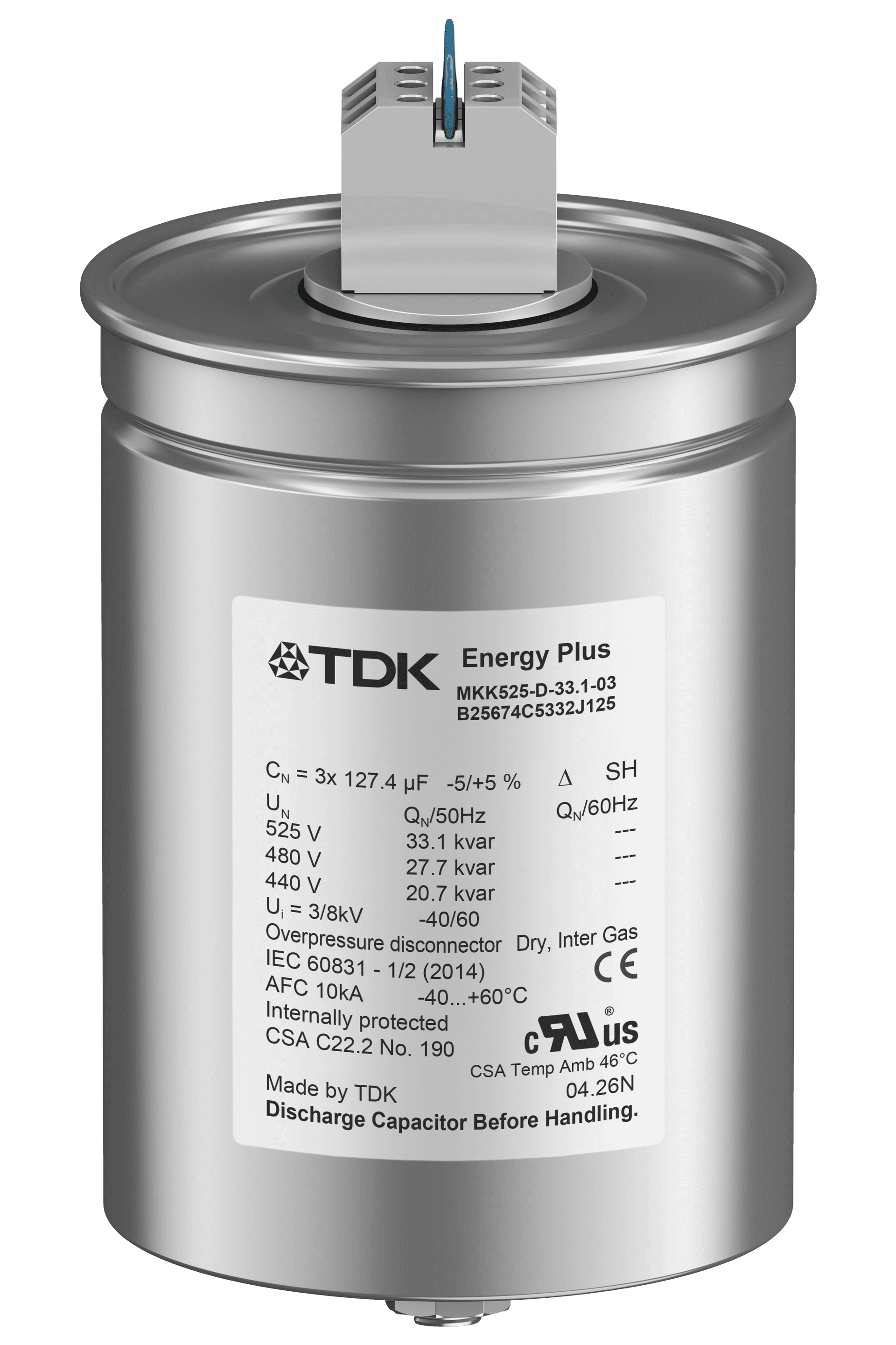
EPCOS
PhaseCap Energy Plus (Resin)
Power capacitor, MKK series (B25675C), semi-dry biodegradable resin · EPCOS AG / TDK Electronics
EPCOS
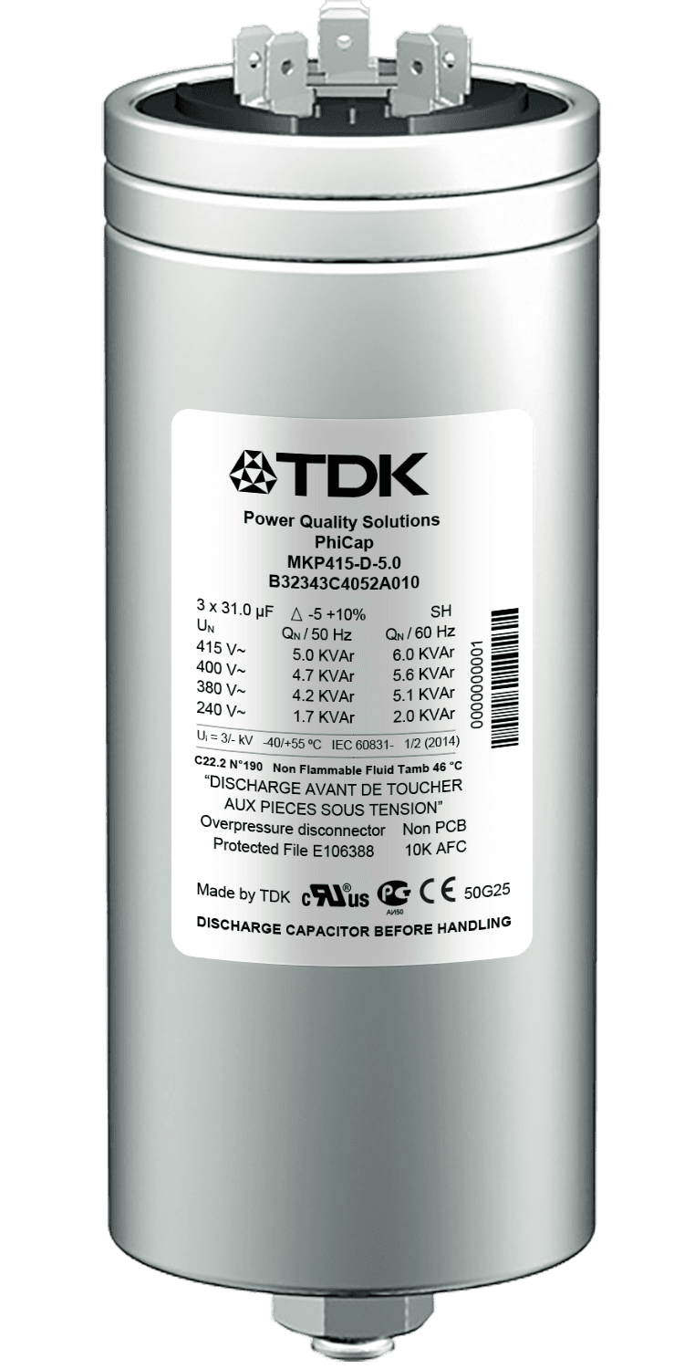
PhiCap
Power capacitor, MKP series (B32340C / B32343C / B32344E) · EPCOS AG / TDK Electronics
EPCOS
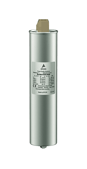
DeltaCap
Power capacitor, MKD series (B32304A), 480 V / 33 kvar · EPCOS AG / TDK Electronics
Get in Touch
Contact us about this product
Let us work out the right model for your application. Share your single-line diagram or measurement data and our technical team will review it.