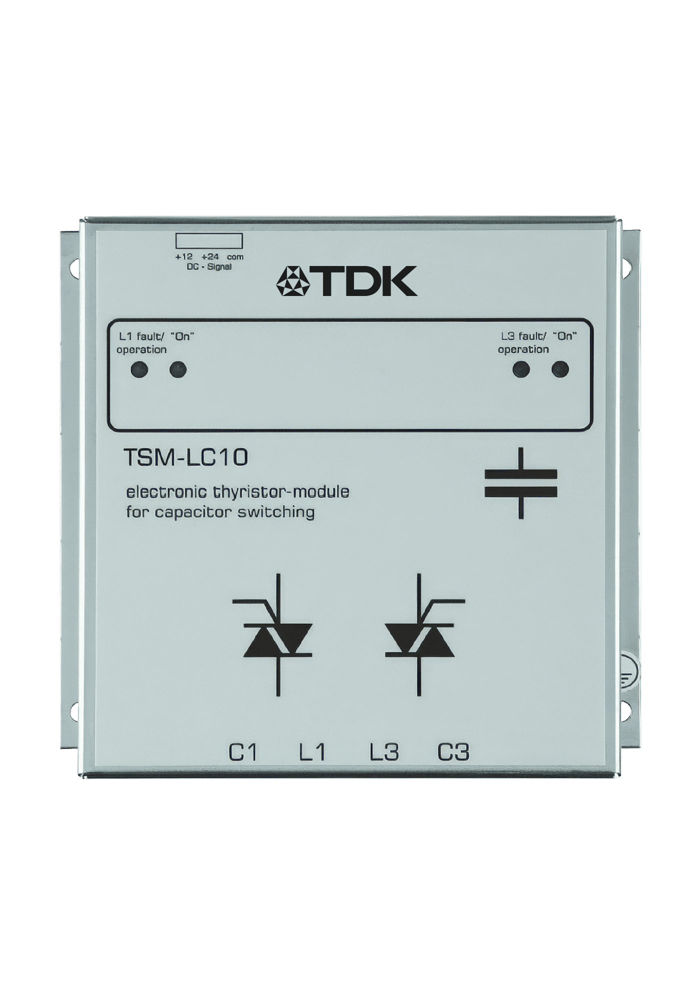
TSM-LC
Thyristor switching modules for dynamic PFC, TSM-LC series, 10 … 100 kvar · EPCOS AG / TDK Electronics
A conventional compensation panel switches its steps with contactors, and contactors have a fixed number of operations in them — between 100 000 and 200 000 over their whole life. On a press line, a spot welder, a crane or a lift, the reactive power demand changes on a millisecond scale and the switching count needed can reach 100 000 a year, which burns out both the contactor and the capacitor within a year or two. Worse, IEC 60831 allows a low-voltage capacitor only 5000 switching operations a year, so the capacitor gives up first. The TSM-LC series is the answer to that: an electronic switch in place of the mechanical one. Each module is a fast, self-monitoring thyristor switch for capacitive loads that connects a capacitor step within about 5 ms, with effectively no limit on the number of operations because there is nothing to wear. It holds the capacitor at the peak value of the grid voltage and connects it only when the grid reaches that same peak, so the step is switched current-free — the inrush currents of up to 200 × IN that a contactor has to damp simply never occur, and the 75-second discharge wait of a conventional bank is not needed either. The module carries its own intelligence: it monitors voltage, phase sequence, capacitor output and temperature continuously and reports operation and faults on two LEDs per phase. Triggering is a 10 … 24 V DC signal from a transistor-output PF controller such as BR6000-T or BR7000-T, a PLC, or the process itself; the TSM-LC-S variant is triggered over the system bus from a BR7000-I-TH/S485, which also displays and monitors up to 32 modules from the controller. Epkom holds the TSM-LC10, TSM-LC-N and TSM-LC-N1; the rest of the range is available to order.
Key Features
- 01Output range 10 … 100 kvar, voltage range 200 … 690 V AC depending on the variant, 50/60 Hz
- 02Reaction time 5 milliseconds; virtually no limit on the number of switching operations
- 03Zero-current switching: no inrush current, no transients, no switching noise, no mechanical wear
- 04Permanent self-monitoring of voltage, phase sequence, capacitor output and temperature; 2 LEDs per phase
- 05Installed like a contactor; all the intelligence is inside the module
- 06Triggered by 10 … 24 V DC from a transistor-output PF controller, a PLC or the process
- 07TSM-LC-S variant triggered over the system bus from a BR7000-I-TH/S485: up to 32 modules displayed and monitored at the controller
- 08Suitable for tuned and detuned as well as conventional systems; maintenance-free, passively cooled
Applications
- Low Voltage Reactive Power Compensation SolutionsIn industrial and commercial facilities the reactive power balance can be upset both by inductive loads such as motors and transformers and by loads with a capacitive effect such as UPS systems, drives and long cable runs. This can disturb the reactive power balance, move the power factor away from the desired level, draw unnecessary current from the network, increase losses and incur reactive energy charges. Low voltage compensation systems hold the power factor at the desired level by providing compensation matched to the facility's inductive or capacitive reactive power demand. Where load changes are rapid, thyristor-switched systems are used to respond quickly to reactive power variation. In facilities where harmonics are present, compensation systems with harmonic filter reactors are applied to keep the capacitors from entering resonance with the network. A correctly engineered compensation system helps to avoid reactive energy charges, to use transformer and cable capacity more effectively, to reduce electrical losses and to improve system performance.
- SVC and STATCOM SolutionsSVC and STATCOM systems provide dynamic reactive power compensation and voltage control in facilities where reactive power demand changes rapidly and continuously. They are effective above all in applications where the response time of conventional compensation systems is not sufficient. SVC systems work with thyristor-controlled reactive power elements, while STATCOM systems, built on power electronics converter technology, respond very quickly and can provide effective reactive power support even at low network voltages. In applications with rapid load changes such as arc furnaces, rolling mills, large motor loads and renewable energy plants, they help to reduce voltage fluctuation and flicker as well as controlling reactive power. SVC and STATCOM solutions are designed specifically for each project, evaluating the facility's power demand, load characteristic, network structure and power quality measurements. With the right system selection, voltage stability is improved, reactive power flow is brought under control and the facility's adverse effects on the network are reduced.
Technical Specifications
TSM-LC
| Variants and ordering codes | TSM-LC10: B44066T0010E402. TSM-LC-N: B44066T3050R402. TSM-LC-N1: B44066T3850E402. TSM-LC-N480: B44066T3850E408. TSM-LC-N690: B44066T3050E690. TSM-LC100: B44066T0100E402. TSM-LC-I: B44066T1022E520 |
|---|---|
| Types held by Epkom | TSM-LC10, TSM-LC-N, TSM-LC-N1 |
| Rated voltage | TSM-LC10 and TSM-LC100: 380 … 400 V AC. TSM-LC-N: 380 … 400 V AC. TSM-LC-N1: 380 … 440 V AC. TSM-LC-N480: 380 … 480 V AC. TSM-LC-N690: 380 … 690 V AC. TSM-LC-I: 230 … 525 V AC. TSM-LC-S: 200 … 440 V AC |
| Maximum power at nominal voltage | TSM-LC10: 12.5 kvar. TSM-LC-N: 50 kvar. TSM-LC-N1: 25 … 50 kvar. TSM-LC-N480: 50 kvar. TSM-LC-N690: 40 … 75 kvar. TSM-LC100: 100 kvar. TSM-LC-I: 10 … 22 kvar |
| Frequency | 50 / 60 Hz |
| Switching time | Approx. 5 ms |
| Re-switching time | Depends on the detuning factor and the discharge resistor used |
| Triggering | 10 … 24 V DC (approx. 10 mA) via terminal clamp, internally galvanically decoupled; TSM-LC-S over the system bus |
| Neutral required | No |
| Auxiliary supply | Not required on TSM-LC10, TSM-LC-N and TSM-LC-N1; 230 V AC / 10 VA on TSM-LC-N480 and TSM-LC-N690; 230 V AC for the fan on TSM-LC100 |
| Power loss | Pv (W) = 2.0 × I (A); approx. 35 W at 400 V / 12.5 kvar, approx. 150 W at 400 V / 50 kvar, typically 300 W on TSM-LC100. TSM-LC-N690: Pv = 2.4 × I, approx. 150 W at nominal current |
| Recommended fuses, superfast | 3 × electronic fuse (NH00 AC 690 V): 35 A at 12.5 kvar, 63 A at 25 kvar, 125 A at 50 kvar; 3 × NH1 (AC 690 V) 250 A / 125 A on TSM-LC100 |
| Monitoring / display | Voltage, phase sequence, capacitor output, operating status and temperature; 2 LEDs per phase. After a temperature fault the heat sink must fall below +50 °C before re-switching |
| Ambient temperature | −10 … +55 °C at nominal load |
| Power circuit / connection | Direct 4-pole connection from the bottom: terminal clamps on TSM-LC10, high-current clamps (cable lug 35 mm²) on the N types, high-current plug on TSM-LC-N690, busbar (cable lug 70 mm²) on TSM-LC100 |
| Dimensions w × h × d | TSM-LC10: 163 × 152 × 75 mm. TSM-LC-N: 157 × 200 × 175 mm. TSM-LC-N1 / N480: 157 × 200 × 180 mm. TSM-LC-N690: 157 × 200 × 190 mm. TSM-LC100: 157 × 240 × 195 mm |
| Weight | 1.75 kg (TSM-LC10); approx. 4.8 kg (N types); 5.5 kg (TSM-LC100) |
| Mounting | Directly on the mounting plate, vertical, minimum 150 mm clearance above and below; modules must not be stacked one above the other |
| Required accessories — discharge resistors | EW-22 high-voltage discharge resistor: 1 per step on TSM-LC10 / N / N1 / N480, 2 on TSM-LC-N690, 1 – 2 in parallel on TSM-LC100 |
| Required accessories — current limitation reactors | In systems without detuning reactors: 2 × BD100 per module (TSM-LC100 requires a special current limitation reactor) |
| Applications | Presses, welding machines, elevators, cranes, wind turbines and other main supply networks with high load fluctuations |
Technical values are taken from the manufacturer's published documentation. Confirm against the current datasheet before ordering.
Downloads
Datasheets, manuals and technical documentation are available from the manufacturer's document centre, or on request from us.
Technical sources
- www.tdk-electronics.tdk.com/download/174004/af7615a46f93c0fa639ca0b108748f46/pfc-katalog-pp.pdf
- www.tdk-electronics.tdk.com/inf/20/50/ds/B44066T3050R402.pdf
- www.tdk-electronics.tdk.com/inf/20/50/ds/B44066T3850E402.pdf
- www.tdk-electronics.tdk.com/inf/20/50/ds/B44066T3050E690.pdf
- www.tdk-electronics.tdk.com/en/530290/products/product-catalog/components-for-power-factor-correction-and-harmonic-filtering/key-components-thyristor-modules
Related Products
Thyristor Modules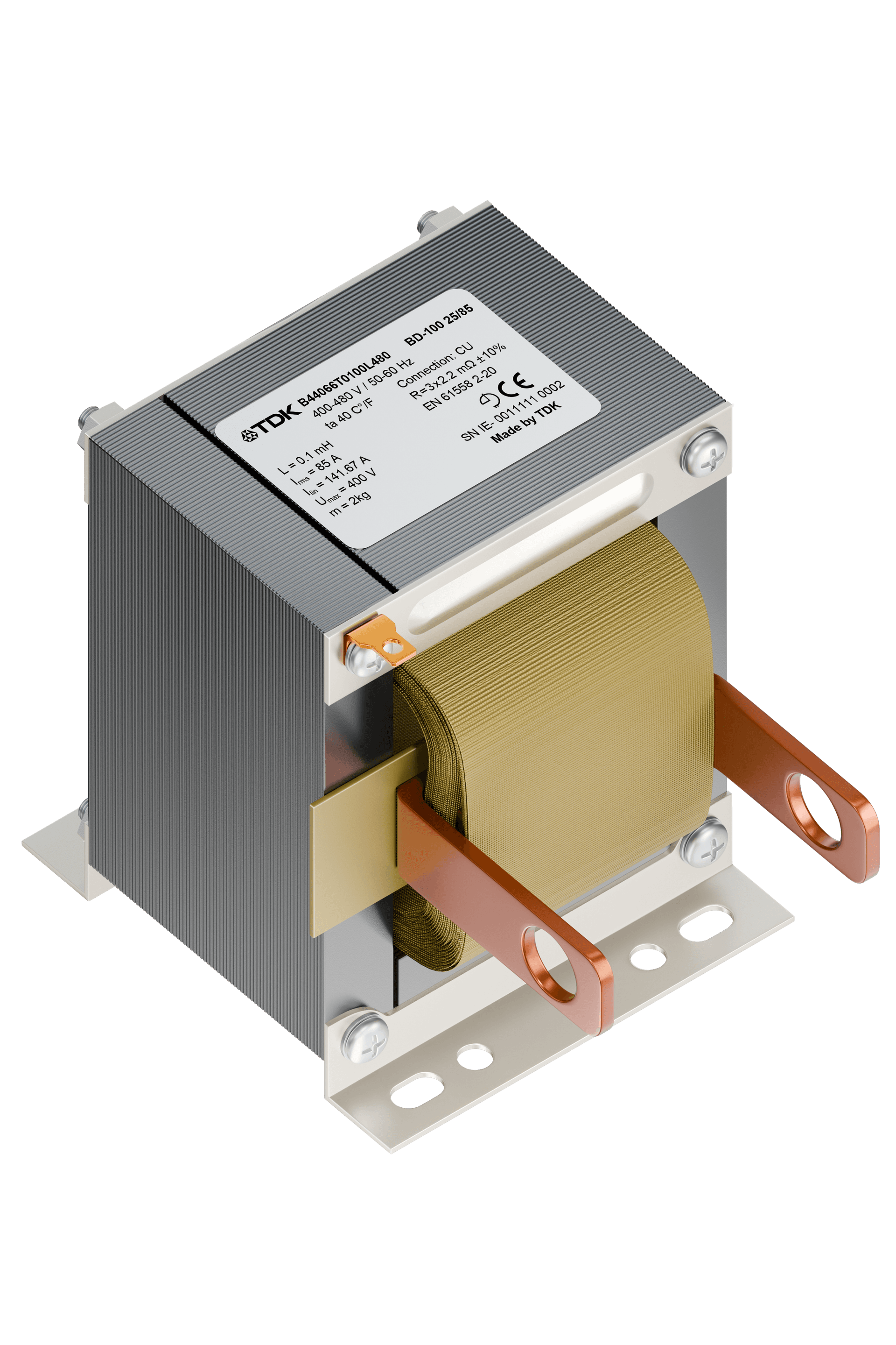
EPCOS
BD-100
Current limitation reactor for TSM thyristor modules, BD series · EPCOS AG / TDK Electronics
EPCOS
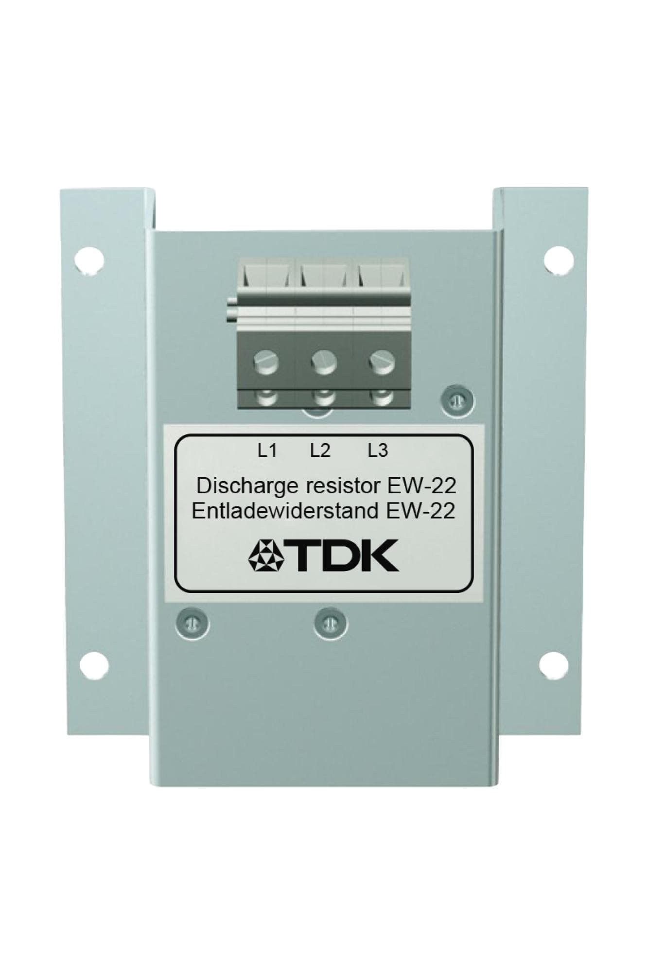
EW-22
Discharge resistor for dynamic PFC capacitors · EPCOS AG / TDK Electronics
EPCOS
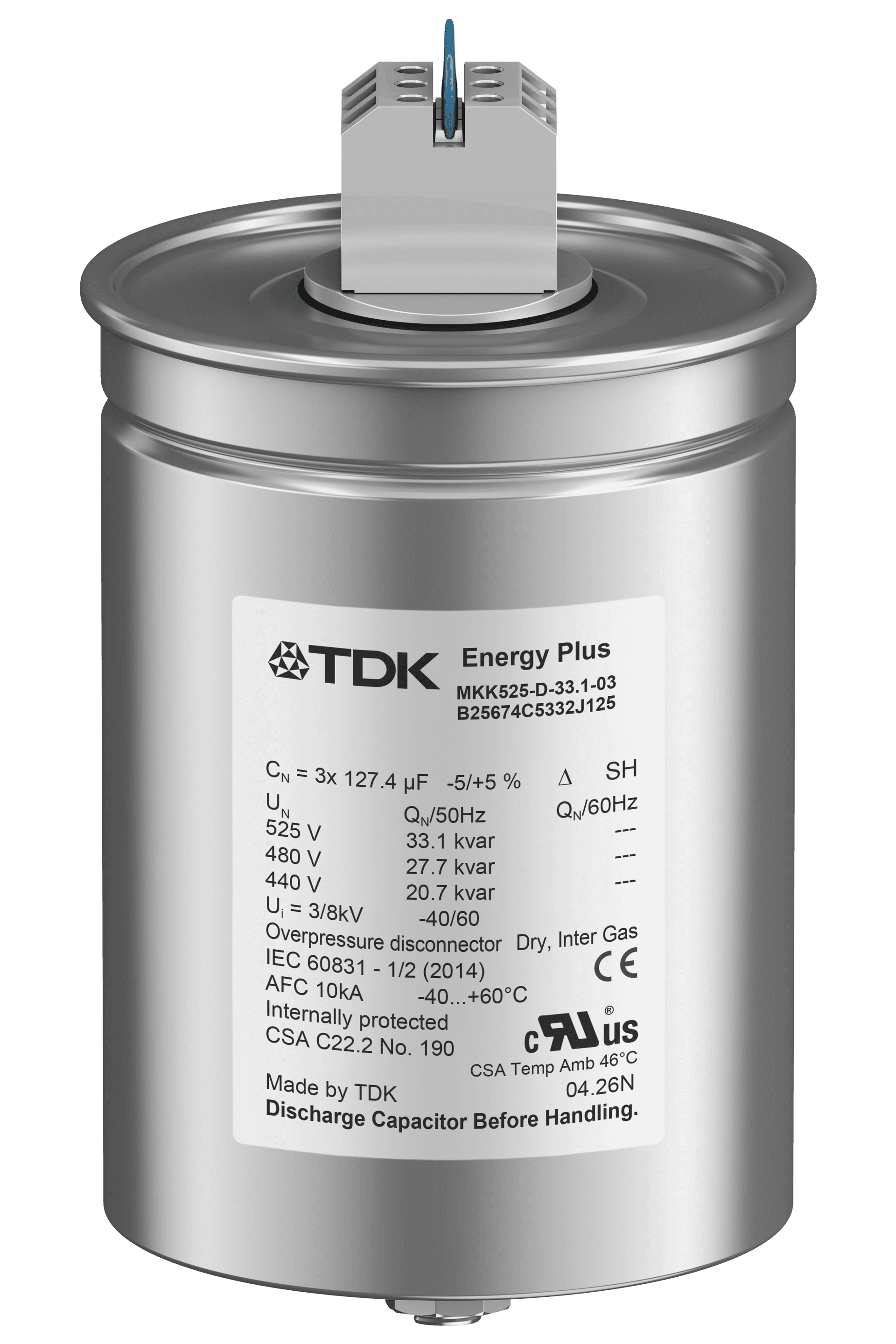
PhaseCap Energy Plus (Resin)
Power capacitor, MKK series (B25675C), semi-dry biodegradable resin · EPCOS AG / TDK Electronics
Get in Touch
Contact us about this product
Let us work out the right model for your application. Share your single-line diagram or measurement data and our technical team will review it.