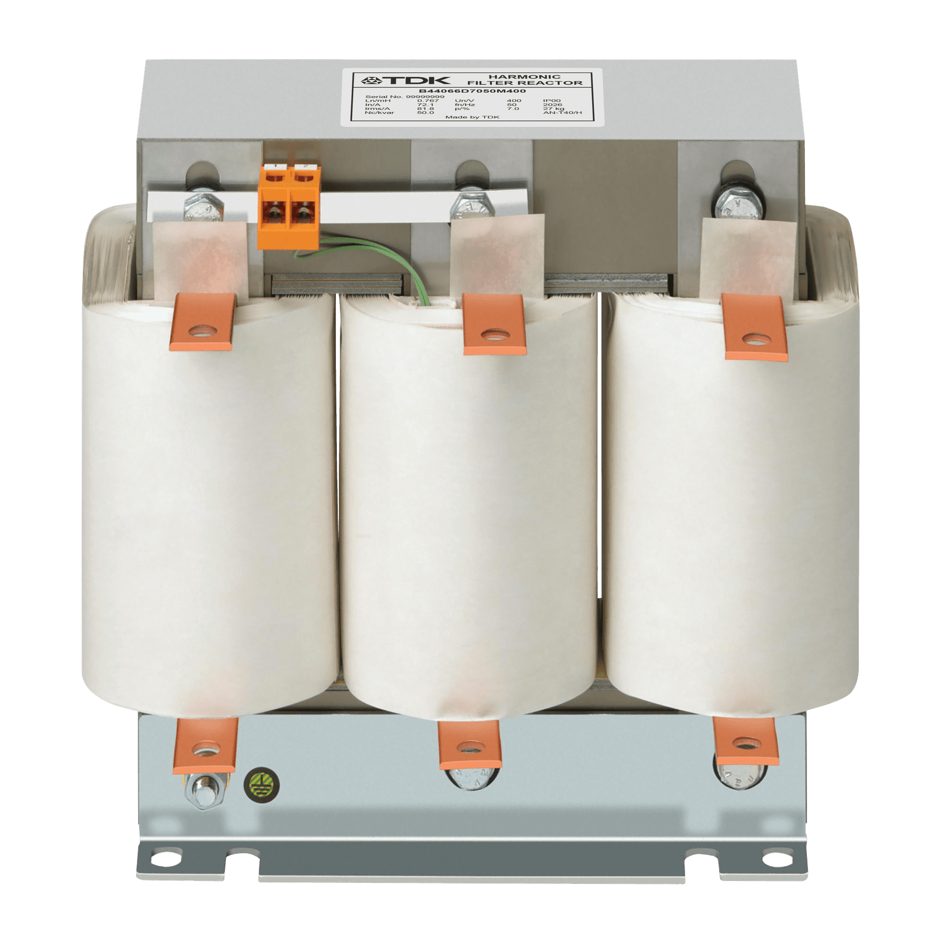
B44066D
Detuned reactors — antiresonance harmonic filter, B44066D series, 10 … 100 kvar · EPCOS AG / TDK Electronics
A power capacitor and the feeding transformer form a resonant circuit whether anyone intended it or not, and experience puts its self-resonant frequency between 250 and 500 Hz — right on top of the 5th and 7th harmonics that drives, UPS systems and electronic ballasts put onto the network. When that resonance is excited the current in both branches climbs, the capacitors and the transformer are overloaded, harmonics are amplified rather than absorbed, and metering, control systems and computers start misbehaving. The B44066D series prevents it. A three-phase reactor connected in series with each capacitor step moves the resonant frequency of that branch below the lowest harmonic present, so the branch is inductive to every harmonic above it and purely capacitive at 50 or 60 Hz, where the reactive power is actually wanted. Beyond that, the reactor and capacitor together form a series resonant circuit that offers a low-impedance path at its tuning frequency, so part of the harmonic current is drawn off the network rather than left to circulate. The series covers 10 to 100 kvar at 400 and 440 V in three detuning factors — 5.67 %, 7 % and 14 % — with high linearity, low losses and a temperature micro switch wound into the inner coil. Epkom's photographed unit is the B44066D7050M400: 7 % detuning, 50 kvar, 400 V, 50 Hz.
Key Features
- 01Output range 10 … 100 kvar at 400 and 440 V, 50 or 60 Hz
- 02Three detuning factors: 5.67 % (fr = 210 Hz), 7 % (fr = 189 Hz) and 14 % (fr = 135 Hz) at 400 V / 50 Hz
- 03High linearity to avoid choke tilt: inductance holds to 2.08 × I1 at 5.67 %, 1.73 × I1 at 7 %, 1.37 × I1 at 14 %
- 04High harmonic loading capability and very low losses
- 05Temperature protection: micro switch (NC contact) wound into the inner coil
- 06Low noise, convenient mounting, long expected life time
- 07Separate terminals for line, capacitors and temperature contact
- 08Three-phase filter reactors to VDE 0532 / EN 60289
Applications
- Low Voltage Reactive Power Compensation SolutionsIn industrial and commercial facilities the reactive power balance can be upset both by inductive loads such as motors and transformers and by loads with a capacitive effect such as UPS systems, drives and long cable runs. This can disturb the reactive power balance, move the power factor away from the desired level, draw unnecessary current from the network, increase losses and incur reactive energy charges. Low voltage compensation systems hold the power factor at the desired level by providing compensation matched to the facility's inductive or capacitive reactive power demand. Where load changes are rapid, thyristor-switched systems are used to respond quickly to reactive power variation. In facilities where harmonics are present, compensation systems with harmonic filter reactors are applied to keep the capacitors from entering resonance with the network. A correctly engineered compensation system helps to avoid reactive energy charges, to use transformer and cable capacity more effectively, to reduce electrical losses and to improve system performance.
- Harmonic Filter SolutionsNonlinear loads such as frequency converters, rectifiers, UPS systems, power electronics equipment and arc furnaces can cause current and voltage harmonics on the network. High harmonic levels lead to overheating in transformers, cables and capacitors, to increased energy losses, to a risk of resonance and to unexpected failures in sensitive equipment. Harmonics are reduced with active or passive harmonic filter solutions selected according to the facility's load structure and harmonic spectrum. Passive harmonic filters are effective at reducing specific harmonic components, while active harmonic filters compensate harmonics in real time under variable load conditions, providing dynamic filtering. At EPKOM we determine the filter type and capacity that suits the facility from power quality measurements and harmonic analysis, and engineer our solutions taking IEEE 519 and the relevant IEC/EN standards into account. This reduces harmonic levels, protects equipment and allows the electrical system to run more safely and efficiently.
Technical Specifications
B44066D
| Series / ordering code | B44066D + detuning digits (5 = 5.67 %, 7 = 7 %, 14 = 14 %) + output + voltage code, e.g. B44066D7050M400 = 7 %, 50 kvar, 400 V. Voltage code 400 or 440 for 50 Hz, 441 for 440 V / 60 Hz |
|---|---|
| Output range | 10 · 12.5 · 20 · 25 · 40 · 50 · 75 · 100 kvar (25 … 100 kvar at 440 V / 60 Hz) |
| Rated voltage | 400 V and 440 V; other voltages on request |
| Rated frequency | 50 Hz or 60 Hz |
| Detuning factor p | 5.67 %, 7 %, 14 % |
| Tuning frequency fr at 50 Hz | 210 Hz (p = 5.67 %), 189 Hz (p = 7 %), 135 Hz (p = 14 %) |
| Inductance L — 400 V, 50 Hz, p = 7 % | 3.84 mH at 10 kvar down to 0.38 mH at 100 kvar (3.01 / 1.92 / 1.53 / 0.96 / 0.77 / 0.51 mH at 12.5 / 20 / 25 / 40 / 50 / 75 kvar) |
| Delta capacitance — 400 V, 50 Hz, p = 7 % | 3 × 61 µF at 10 kvar up to 3 × 617 µF at 100 kvar |
| Effective current IRMS — 400 V, 50 Hz, p = 7 % | 16.4 · 20.5 · 32.7 · 40.9 · 65.4 · 81.8 · 122.7 · 163.3 A (10 … 100 kvar) |
| Total losses | 65 … 470 W depending on rating and detuning factor (400 V, 50 Hz, p = 7 %: 70 … 390 W) |
| Weight | 5.9 … 66 kg depending on rating and detuning factor |
| Effective current definition | IRMS = √(I1² + I3² … I13²) |
| Fundamental current | I1 = 1.06 × IR (50 Hz or 60 Hz current of the capacitor) |
| Rated harmonic voltages | V3 = 0.5 %, V5 = 6.0 %, V7 = 5.0 %, V11 = 3.5 %, V13 = 3.0 % of VR at 100 % duty cycle (DIN ENV VV61000-2-2) |
| Temperature protection | Micro switch (NC contact) in the inner coil — warning device only, does not disconnect the reactor |
| Cooling / ambient temperature | Natural / +40 °C |
| Class of protection / enclosure | Class I / IP00 |
| Terminals | 10 mm² or 16 mm² terminal blocks on the smaller ratings; M6 / M8 aluminium flat bars or Cu bars ø 9 / ø 11 mm on the larger ones |
| Connections | Line 1U1-1V1-1W1; capacitors 1U2-1V2-1W2; temperature contact terminals 1-2 |
| High VTHD variants | For networks with 12 %, 16 % or 20 % voltage distortion: 25 … 50 kvar at 400 / 440 V, aluminium foil winding, linearity up to 250 % of rated current, class H, losses 120 … 330 W (ordering codes B44066D7025E412, B44066D7050E412 / E416 / E420, B44066D1450E412, B44066D7025E452) |
| Standards | VDE 0532 / EN 60289; High VTHD variants to IEC 60076-6 |
Technical values are taken from the manufacturer's published documentation. Confirm against the current datasheet before ordering.
Downloads
Datasheets, manuals and technical documentation are available from the manufacturer's document centre, or on request from us.
Technical sources
- www.tdk-electronics.tdk.com/download/174004/af7615a46f93c0fa639ca0b108748f46/pfc-katalog-pp.pdf
- www.tdk-electronics.tdk.com/inf/20/50/ds/B44066D7050M400.pdf
- www.tdk-electronics.tdk.com/en/530284/products/product-catalog/components-for-power-factor-correction-and-harmonic-filtering/key-components-reactors
Related Products
Harmonic Filter Reactors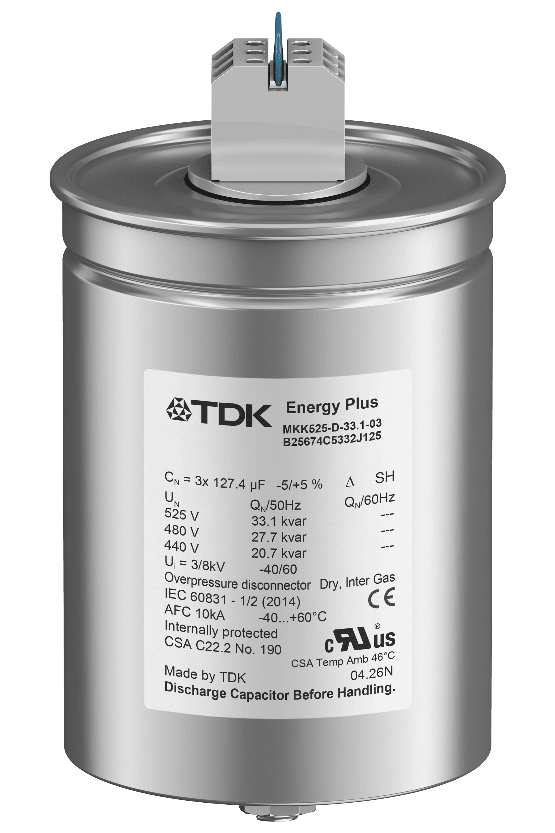
EPCOS
PhaseCap Energy Plus (Resin)
Power capacitor, MKK series (B25675C), semi-dry biodegradable resin · EPCOS AG / TDK Electronics
EPCOS
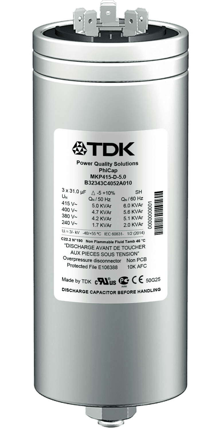
PhiCap
Power capacitor, MKP series (B32340C / B32343C / B32344E) · EPCOS AG / TDK Electronics
EPCOS
DeltaCap
Power capacitor, MKD series (B32304A), 480 V / 33 kvar · EPCOS AG / TDK Electronics
Get in Touch
Contact us about this product
Let us work out the right model for your application. Share your single-line diagram or measurement data and our technical team will review it.