BR6000 / BR7000 / Prophi
Reactive power (power factor) controllers, 6 … 15 steps · EPCOS AG / TDK Electronics and Janitza Electronics GmbH
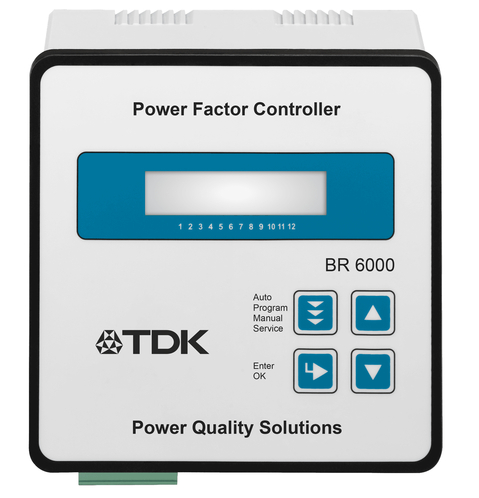
The power factor controller is the part of a compensation panel that decides what happens: it measures the actual power factor through a current transformer and switches capacitor steps in and out to hold the target cos φ. Epkom supplies three families, all panel-mounted with an illuminated display and menu-driven operation in plain language, Turkish included, and all of them switch either contactors (relay outputs) or thyristor modules for dynamic compensation (transistor outputs). BR6000 is the mainstream controller and the one most panels are built around: 6 or 12 relay outputs, or 6 transistor outputs on the -T6, with the widest measuring voltage range of the three at 30 … 525 V. BR7000 is the higher-end model, with up to 15 outputs, two independent isolated RS485 interfaces, harmonic analysis to the 31st order and an oscilloscope-style waveform display for looking at what the network is actually doing. Prophi, from Janitza, offers 6 or 12 outputs in relay, transistor and hybrid versions, and adds Profibus DP alongside Modbus RTU where the panel has to report into plant automation. What the range gives you is a choice of step count and of intelligence: all of them run self-optimizing control that works out which combination of steps to switch rather than simply stepping up and down a list, which reduces switching operations and, with them, the wear on the capacitors and their contactors.
Key Features
- 016 to 15 switching steps, in relay, transistor and mixed (relay + transistor) versions
- 02Transistor versions drive TSM thyristor modules for dynamic compensation
- 03Self-optimizing intelligent control, plus series (LIFO) and circular (FIFO) switching
- 0420 preset control series (23 on BR7000) and a control series editor for free programming
- 05Four-quadrant operation, e.g. on sites with a standby generator
- 06Wide measuring range: 30 … 525 V AC on BR6000, 30 … 440 V (L-N) / 50 … 760 V (L-L) on BR7000
- 07Measures and displays V, A, kvar, kW, kVA, frequency, energy, temperature, real-time and target cos φ, THD-V, THD-I and individual harmonics
- 08Records maxima, capacitor switching cycles and capacitor operating time; internal error storage
- 09RS485 (Modbus RTU) on BR7000 /S485, BR7000 and Prophi RS variants; Profibus DP V0 on Prophi
- 10Menu-driven operation in plain language including Turkish; panel-mounted 144 × 144 mm
Applications
- Low Voltage Reactive Power Compensation SolutionsIn industrial and commercial facilities the reactive power balance can be upset both by inductive loads such as motors and transformers and by loads with a capacitive effect such as UPS systems, drives and long cable runs. This can disturb the reactive power balance, move the power factor away from the desired level, draw unnecessary current from the network, increase losses and incur reactive energy charges. Low voltage compensation systems hold the power factor at the desired level by providing compensation matched to the facility's inductive or capacitive reactive power demand. Where load changes are rapid, thyristor-switched systems are used to respond quickly to reactive power variation. In facilities where harmonics are present, compensation systems with harmonic filter reactors are applied to keep the capacitors from entering resonance with the network. A correctly engineered compensation system helps to avoid reactive energy charges, to use transformer and cable capacity more effectively, to reduce electrical losses and to improve system performance.
- Medium Voltage Reactive Power Compensation SolutionsMedium voltage compensation systems hold the power factor at the desired level in high-power industrial facilities by supplying the reactive power that inductive loads require within the plant itself. This reduces the reactive power drawn from the network, lowers electrical losses and makes more efficient use of existing system capacity. MV compensation systems can use fixed or automatically stepped capacitor banks according to the needs of the facility. Switching is carried out by vacuum contactors or circuit breakers, and the system is operated safely with appropriate protection and control equipment. Because every facility has a different network structure, load characteristic and reactive power demand, MV compensation systems are engineered specifically for the site rather than supplied as a standard solution. Capacitor rating, step structure, switching devices, the protection system and, where required, series reactors are determined from the measurement and engineering work carried out, producing a compensation system suited to the facility's operating conditions.
Technical Specifications
BR6000 / BR7000 / Prophi
| Models and ordering codes — BR6000 | BR6000-R6, 6 relay outputs: B44066R6006E230. BR6000-R12, 12 relay outputs: B44066R6012E230. BR6000-T6, 6 transistor outputs: B44066R6106E230 |
|---|---|
| Models and ordering codes — BR7000 | BR7000-I, 12+1 relay: B44066R7012E230. BR7000-I/S485: B44066R7112E230. BR7000-I-TH, 12 relay + 12 transistor: B44066R7412E230. BR7000-I-TH/S485: B44066R7612E230. BR7000, 15 relay + 2 × RS485: B44066R7415E230. BR7000-T, 15 transistor + 2 × RS485: B44066R7615E230 |
| Models — Prophi | Prophi 6R / 12R (relay), 6T / 12T (transistor), 6T6R (hybrid), 12RS / 12TS (with RS485) |
| Number of steps | 6, 12, 12+1 or 15 depending on the model |
| Supply voltage | BR6000: 110 … 230 V AC ±15 %, 50/60 Hz. BR7000: 110 … 440 V AC ±15 % (BR7000-I-TH: 110 … 230 V AC). Prophi: 400 V AC standard, variants for 100 / 110 / 200 / 230 / 440 V AC |
| Measurement voltage range | BR6000: 30 … 525 V AC (L-N or L-L). BR7000: 30 … 440 V AC (L-N), 50 … 760 V AC (L-L); three-phase measurement on BR7000 / BR7000-T |
| Measurement current | x/5 A or x/1 A, selectable; sensitivity 50 mA / 10 mA |
| Fundamental frequency | 50 / 60 Hz |
| Power consumption | BR6000 < 5 VA; BR7000 < 3 W; BR7000-I and BR7000-I-TH < 5 W |
| Display | BR6000: illuminated LCD, 2 × 16 characters. BR7000: illuminated full graphic display, 128 × 64 dots, with display editor and oscilloscope mode. Prophi: high-contrast LCD, approx. 100 measured values |
| Menu languages | Czech, Dutch, German, English, French, Polish, Portuguese, Russian, Spanish, Turkish |
| Harmonic analysis | BR6000: to the 19th order. BR7000: up to the 31st order; BR7000-I / -I-TH odd to the 33rd, even and odd to the 17th. Prophi: 1st … 19th |
| Alarm and message relay | 1 alarm relay; additional freely programmable message relay on BR6000-R12 and BR7000 variants with interface |
| Interface | RS485 (Modbus RTU) on BR7000-I/S485, BR7000-I-TH/S485; 2 independent isolated RS485 on BR7000 / BR7000-T; Prophi: Modbus RTU up to 115.2 kBit/s, Profibus DP V0 1.5 MBit/s, optional RS485 |
| Control modes | Series switching (LIFO), circular switching (FIFO), self-optimizing intelligent control |
| Number of control series | 20 preset on BR6000 and BR7000-I; 23 preset on BR7000; control series editor on all |
| Target cos φ | 0.3 inductive … 0.3 capacitive, adjustable |
| Switching time | Relay outputs 1 … 1200 s; transistor outputs 20 … 1000 ms |
| Alarm functions | Insufficient compensation, overcompensation, undercurrent, overcurrent, over-temperature, harmonics exceeded; programmable threshold; internal error storage |
| Recorded values | Max./min. voltage, max. current, max. Q, P, S, max. THD-V / THD-I, max. temperature, capacitor operating time, number of contactor switching operations (with time stamp on BR7000) |
| Suitable for dynamic PFC | Transistor versions only: BR6000-T6, BR7000-T, BR7000-I-TH and BR7000-I-TH/S485 (the latter also drives TSM-LC-S over the interface) |
| Case / mounting | Panel-mounted 144 × 144 × 55 mm (BR7000: 144 × 144 × 50 mm), DIN 43700 / IEC 61554 cutout 138 × 138 mm; weight 1 kg |
| Operating temperature | BR6000: −20 … +60 °C. BR7000: −20 … +70 °C |
| Protection class | IP54 front plate, IP20 rear side (IEC 60529) |
| Accessories | BR7000-SOFT Windows software (included with BR7000), IF8000 interface module, USB/RS485 converter, DataLogSD data logger, NET8000 web server, RJ45 adapters, VIP-X-TP touch panel, UCM-5 pulse module |
Technical values are taken from the manufacturer's published documentation. Confirm against the current datasheet before ordering.
Downloads
Datasheets, manuals and technical documentation are available from the manufacturer's document centre, or on request from us.
Technical sources
- www.tdk-electronics.tdk.com/download/174004/af7615a46f93c0fa639ca0b108748f46/pfc-katalog-pp.pdf
- www.tdk-electronics.tdk.com/inf/20/65/ds/B44066R6_R230.pdf
- www.tdk-electronics.tdk.com/en/530258/products/product-catalog/components-for-power-factor-correction-and-harmonic-filtering/pf-controllers-and-accessories
- exportpagescdn.net/v2/pdfs/product/146ca227-b0ee-11e6-90ca-3a6bba99afcb/power-factor-controllers-prophi-by-janitza-electronics-gmbh.pdf
Get in Touch
Contact us about this product
Let us work out the right model for your application. Share your single-line diagram or measurement data and our technical team will review it.